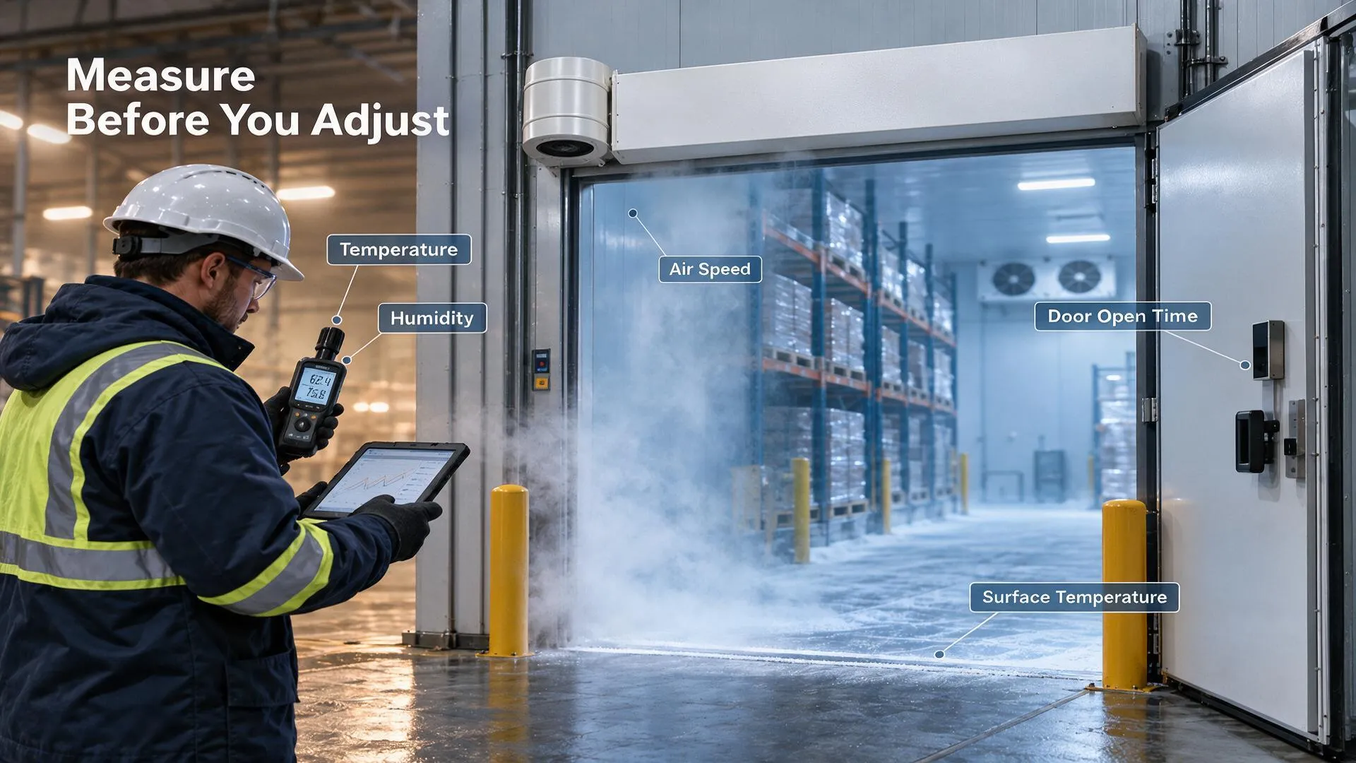
Centrifugal vs Cross-Flow Air Curtains for Cold Rooms
Centrifugal vs Cross-Flow Air Curtains for Cold Rooms Buyers comparing a centrifugal vs cross-flow air curtain often…

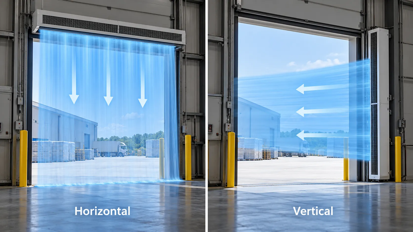
Most air curtains are mounted horizontally above a doorway, but that familiar layout is not automatically best for every factory or warehouse. A very wide opening, limited header space, overhead-door tracks or an excessive nozzle-to-floor distance can make a vertical industrial air curtain worth evaluating. The decision changes jet geometry, structural loads, impact risk and maintenance access, so it should be made during design—not improvised after equipment arrives.
This guide compares horizontal and vertical layouts for large doors. It does not treat either orientation as universally stronger. The correct layout is the one that produces complete, stable coverage at the real opening while remaining safe to install, operate and service.
A horizontal unit discharges downward. Its principal free-jet distance is approximately the nozzle-to-floor height. A vertical unit discharges across the opening. Its principal distance is approximately the clear width for a one-sided layout or part of the width for two opposing sides.
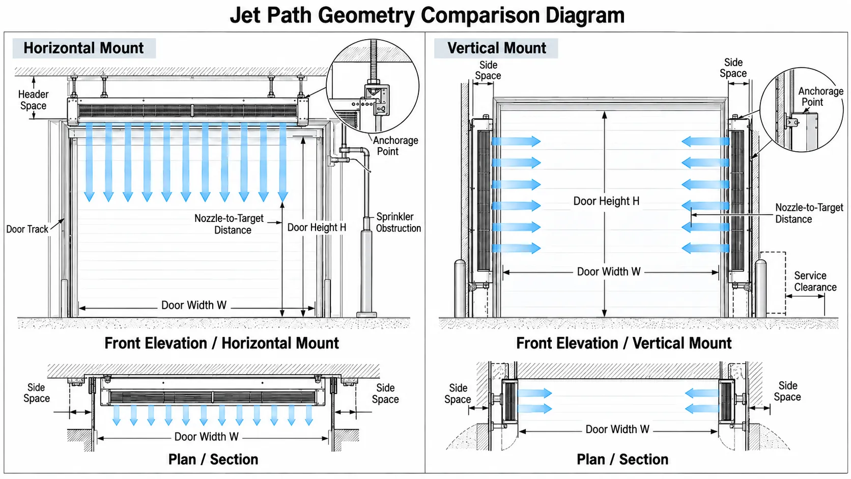
That distinction can be decisive. At a door that is much wider than it is high, a top-mounted jet may have the shorter path. At a very tall, comparatively narrow opening, a side-mounted system may shorten the required throw. Jet distance is not the only variable—buoyancy, wind and traffic direction also affect stability—but it is the first comparison to draw.
Air-curtain performance should be based on tested airflow, velocity uniformity and projection. ANSI/AMCA Standard 220-21 provides the recognized laboratory framework. Ask the manufacturer to relate those data to the proposed orientation and installed distance.
Horizontal mounting keeps equipment out of the vehicle impact zone and uses the floor as the jet’s terminal surface. It is often preferred when:
For wide doors, several units can be mounted in a continuous bank. Their nozzles should align without gaps, and structural deflection should not distort the discharge plane. The bank also needs a coordinated control scheme so all modules operate at the intended speed.

Door springs, tracks, high-speed-door rolls, beams, sprinklers and cable trays commonly occupy the header. Moving the air curtain far above or behind these obstructions may create bypass paths and increase throw distance. A bracket that “makes it fit” is not enough; the revised position must be checked aerodynamically and structurally.
Maintenance is another consideration. Filters, inlets, motors and terminal boxes installed several meters above the floor require a safe access plan. If every inspection needs a lift in an active loading lane, routine maintenance may be delayed.
A side-mounted arrangement may be useful when:
Vertical systems can be installed on one side or both sides. A one-sided jet must cross the entire width and resist forces over that distance. Opposing units shorten each jet path, but their interaction zone must be designed and commissioned; simply pointing two strong jets at one another can create turbulence or an unstable split.
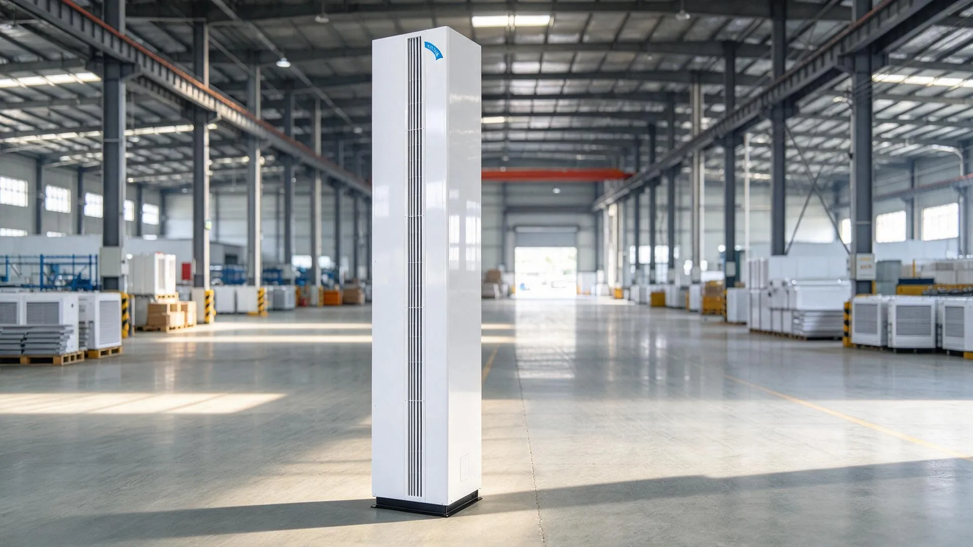
HUANGXI lists a vertical air curtain category for project discussion. The final proposal should include elevation drawings, discharge direction, anchorage, guards and service zones.
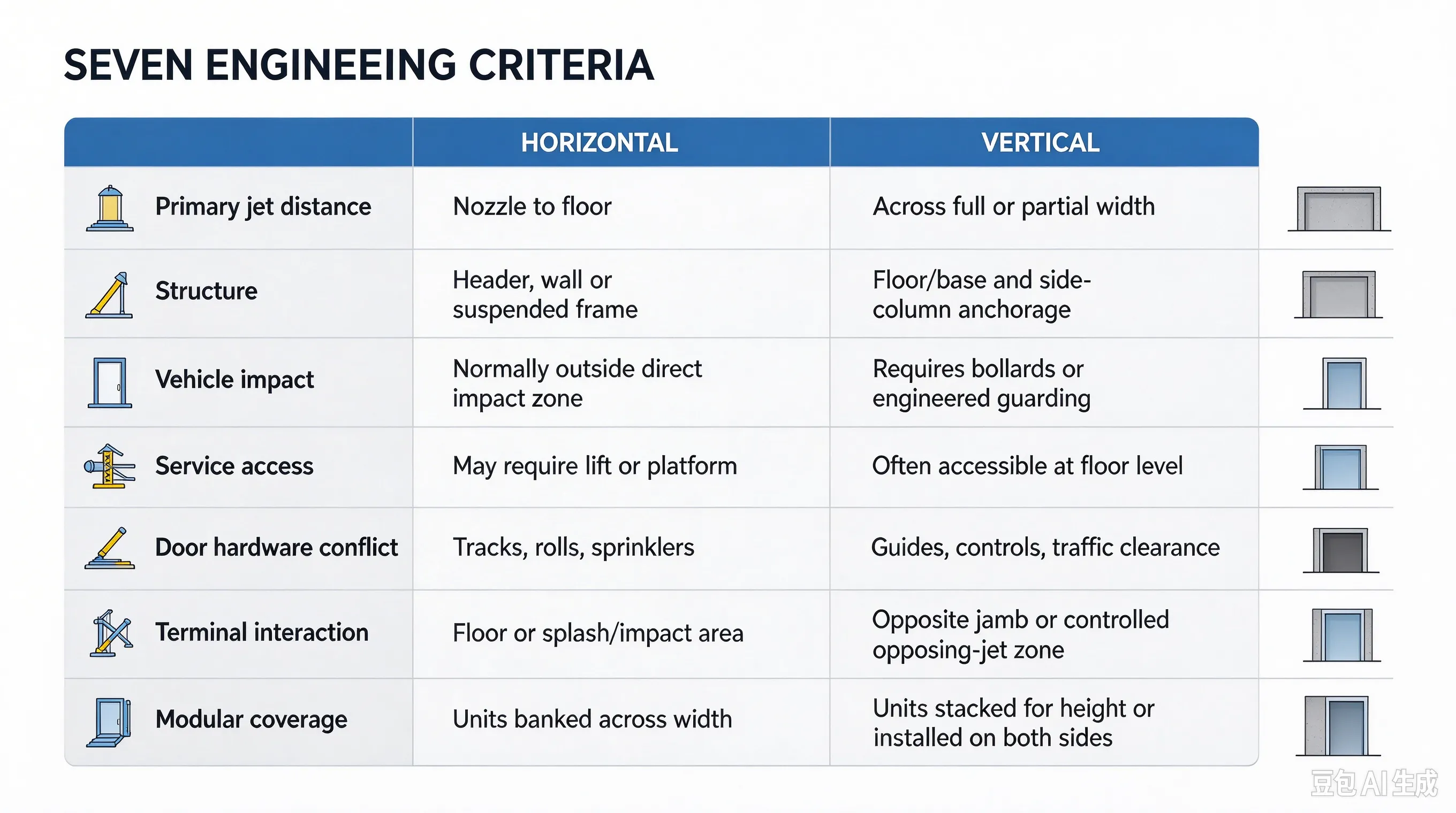
| Criterion | Horizontal | Vertical |
|---|---|---|
| Primary jet distance | Nozzle to floor | Across full or partial door width |
| Structure | Header, wall or suspended frame | Floor/base and side-column anchorage |
| Vehicle impact | Normally outside direct impact zone | Requires bollards or engineered guarding |
| Service access | May require lift or platform | Often accessible at floor level, subject to guards |
| Door hardware conflict | Can conflict with tracks, rolls and sprinklers | Can conflict with guides, controls and traffic clearance |
| Terminal interaction | Floor or splash/impact area | Opposite jamb or controlled opposing-jet zone |
| Modular coverage | Units banked across width | Units stacked for height or installed on both sides |
A vertical unit places valuable rotating equipment near forklifts, pallets and cleaning machines. The design must protect the unit without narrowing the safe opening or creating a collision edge. Include:
Do not place a guard directly in front of the intake or nozzle. A protective structure that restricts airflow changes the fan-system operating point and can undermine the selection.
Turning a unit sideways does not remove the building forces. Warm and cold air still tend to exchange through different parts of a tall opening; wind and mechanical pressure still act across it. The discharge angle and speed must be set for the actual pressure direction.
AMCA’s air-curtain theory and application material explains that velocity projection, uniformity and installation are connected. ASHRAE’s design discussion also includes pressure difference and dynamic efficiency. Those principles should be reflected in the manufacturer’s project calculation or selection rationale.
Changing orientation can alter inlet conditions, bearing loads, drainage and permitted mounting position. Confirm that the specific unit is approved for the proposed orientation. A site team should not rotate a horizontal product 90 degrees unless the manufacturer’s instructions explicitly permit it.
Use fan-curve and tested projection data at the proposed operating speed. The U.S. Department of Energy’s fan-system sourcebook emphasizes that a fan works at the intersection of its performance curve and system resistance. Intake guards, filters, close walls and field-built transitions can change that point.
For either orientation, require:
Start with the published HUANGXI industrial range, then provide the doorway and structure for a project layout. The existing industrial air curtain guide summarizes the current G-series motor and airflow data, while the separate energy article explains why reducing open-door exchange can lower HVAC load.
After installation, verify full coverage with the door in representative operating states. Check for weak zones between modules, excessive entrainment near a wall, recirculation into an intake, and deflection under wind or exhaust. For a two-sided vertical system, observe and measure the meeting region rather than assuming equal fan speeds produce the correct split.
Run typical forklifts through the opening and confirm jet recovery. Inspect vibration, motor current and structural movement. Record the final angle and speed settings so maintenance personnel can restore them after service.
Horizontal mounting is usually the first option because it keeps equipment above traffic and uses the floor as a clear terminal surface. Vertical mounting becomes attractive when header conflicts or extreme height make the downward path impractical. The best orientation balances aerodynamic projection with structure, impact protection, service and control.
To compare layouts, send HUANGXI the clear opening dimensions, header and side-space photos, door drawings, traffic envelope, wind and pressure information, and electrical supply. The proposal should show exactly how the jet covers the opening rather than merely naming an orientation.
No. Confirm permitted orientation with the manufacturer. Bearings, motor cooling, drainage, casing supports and service panels may have been designed for one position.
No. Two sides shorten the individual jet paths but add cost, controls and an interaction zone that must be tuned. One side can be sufficient if tested projection and site forces support it.
As close as the approved mounting and safety clearances permit. Excessive offset can create bypass and exposes the jet to more entrainment before it reaches the opening plane.
Failing to coordinate vehicle protection with airflow. Bollards are essential in many applications, but poorly placed guards can block the intake or discharge and change performance.